After reading this chapter you will be able to describe:
- Define Pump and its types.
- Difference between Pump & Compressor.
- Define Centrifugal Pump and its Working Principal.
- Elaborate Parts of Centrifugal Pump.
- Explain Characteristics of Centrifugal Pump.
- Define cavitations and its reasons.
- Explain the reasons of Pressure losses during Suction.
- Elaborate the reasons of Pressure & Frictions losses in delivery hose lines.
- Find the guidelines for reducing Pressure & frictions losses in delivery hose lines.
- Explain water hammering and its effects.
Pump:
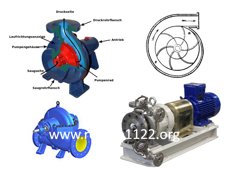
A pump is a machine, driven by some external power, for transmitting energy to fluids. This power may be provided by the operator’s own effort or by coupling the pump to a suitable engine or motor. The Fire Pump are the basic article seen to be important for fire fighter to work on fire vehicles. The working of Fire centrifugal Pump in discussed in detail.
Difference between Pump & Compressor.
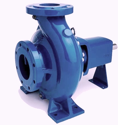
Pump is a mechanical device that transfers Liquid from a lower point to a higher point. E.g. Centrifugal pump, Rotary pump, Reciprocating pump.
Pump is used to increase the pressure of incompressible fluids (i.e., density is constant for change in pressure).
The compressor is a high-pressure mechanical device that compresses air/gas.
The compressor is used to compress the pressure of compressible fluids (i.e. density varies with pressure).
Centrifugal Pump:
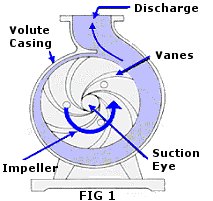
Centrifugal pump is operated by means of an impeller which receives its supply at the centre and discharges it from the periphery.
3.1 Principal Operation:
The principal operation is the centrifugal force by which the liquids rotate.
Parts of Centrifugal Pump (Impeller):
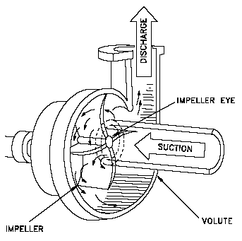
The impeller is a circular metal casting mounted on and rigidly keyed to a central shaft by which it is rotated. Rotation of the impeller causes water to be discharged from the periphery at high velocity by centrifugal force.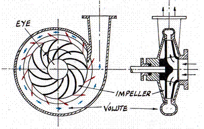
4.1 Parts of Centrifugal Pump (Casing):
An important function of the casing is to convert the kinetic energy of the water when it leaves the impeller into pressure energy. This is done by reducing the velocity of water. 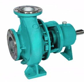
Characteristics of Centrifugal Pump:
At any given speed when there is no flow, the pressure is at a maximum (closed valve pressure). The pressure decreases progressively with an increase in the discharge as the delivery valves are opened. Also, pressure flow increases as the pump speed is increased and vice versa.
Another characteristic is that the horsepower absorbed by the pump increases as the flow increases.
Fire pump are driven by internal combustion engines and will not run at a constant speed for any given throttle setting as the increase in power absorbed and the discharge increases has the effect of reducing the speed of the engine.
Cavitations in Centrifugal Pump:
The formation of vapor bubbles in the pump is known as cavitations and is accompanied by a distinctive rattling sound. This indicates maximum flow condition has been reached and the pump should ease back the throttle until the noise just disappears.
The Vacuum Gauge does not indicate that cavitation conditions have been reached. It registers only the general suction condition in the suction inlet of the pump and is not affected by the low-pressure pockets, which form at the entry to the impeller and the back surfaces of the impeller blades.
6.1 Maximum Theoretical Suction:
1 bar =14.7 psi &
14.7 psi = 760 mm of mercury &
760 mm of mercury = 760*13.6 mm of water (Because mercury is 13.6 time dense than water)
OR
760 * 13.6 mm of water = 760*13.6/25.4 inch of water (Because 25.4mm = 1 inch)
OR
760 * 13.6/ 25.4 inch of water = 760*13.6/25.4*12 feet of water (Because 12inch = 1 feet)
OR
760*13.6/25.4*12 feet of water = 34 feet of water OR
1 bar = 34 feet of water
Rotary Vane Priming Mechanism is installed in our Fire Vehicles to enhance the suction power of centrifugal pumps, but the Maximum Suction Lift of any pump without using foot valve is 34 feet.
Causes of Pressure Loss During Suction:
Factors affecting the pressure condition in the pump are static lift, friction loss in the suction hose and entry losses into the suction strainer and at the suction inlet itself.
7.1 Care & Maintenance of Pump:
Servicing pumps on return from a fire.
Winter maintenance ;
- Anti-freeze mixture.
- Heaters.
- Reserve pumps.
Repairs by station personnel.
Standard tests;
- Monthly output test.
- Monthly vacuum test.
- Suction inspection.
- Six-monthly deep lift test.
Causes of Friction Loss in Delivery Hose Line:
- Rough hose lining.
- Damaged couplings.
- Sharp bends/kinks in hose.
- Adapters.
- Partially closed valves/nozzles.
- Wrong size gasket.
- Excessive hose length.
- Excess flow for hose size.
8.1 Causes of Pressure Loss in Delivery Hose Line:
- Broken hose line.
- Mechanical problems due to poor water supply.
- Error in hydraulics calculation.
- Obstructions from the pump or water main.
- Elevation of the nozzle above the pump.
- 8.2 Some Reasons for Pressure Loss:
- Damaged Couplings.
- Kinks or Sharp Bends.
- Adapters.
- Hose Length. .
- Elevation Loss.
Guidelines for Reducing Friction Loss:
- Check for rough linings in fire hose.
- Replace damaged hose couplings.
- Eliminate sharp bends in hose when possible.
- Use adapters to make hose connections only when necessary.
- Keep nozzles and valves fully open when operating hose lines.
- Use proper size hose gaskets for hose selected.
- Use short hose lines as much as possible.
- Use larger hose or multiple lines when flow must be increased.
9.1 Elevation Loss/Gain:
Nozzle above # Fire Pump = Pressure Loss
( 34 feet Elevation = 01 bar loss)
Nozzle below ♦ Fire Pump = Pressure Gain
Water Hammer:
- Is surge created by suddenly stopping the flow of water through fire hose or pipe.
- Is often heard like a hammer striking pipe.
- Causes a change in direction of energy and multiplies the energy many times.
- Can damage pumps, hose lines, water mains, couplings, nozzles, and hydrants.
- Can be prevented by operating nozzle controls, hydrants, valves, and hose clamps slowly.

John Doe, a seasoned firefighter, shares his vast knowledge of fire safety and emergency preparedness at arescuer.com, aiming to empower and educate
